Foster Walk In Freezers & Coolers
Installation Guide
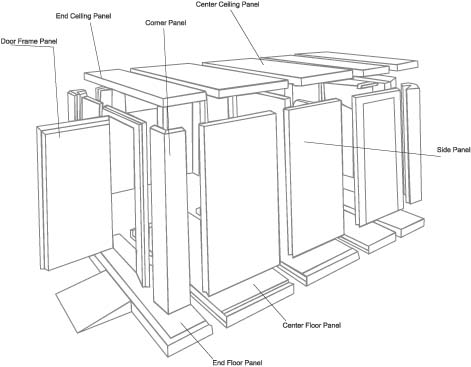
7 Main Panels for Walk-in Coolers and Freezers
Foster manufactures 7 basic panels which are foamed in place with polyuretane, each panel can be made in different sizes, and styles.
WATCH THE INSTALLATION VIDEO
(no audio)
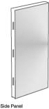
SIDE PANELS
Available in following sizes 8", 20", 24", 36" in various heights.
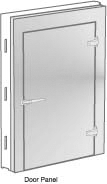
DOOR FRAME PANELS
Available in 48", 60", & 72" widths in various heights.
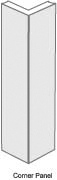
CORNER PANELS
Manufactured as 2 interlocking pieces 12"x12" or 24"x24" in various heights.
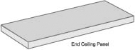
END CEILING PANELS
24" and 36" wide in various lengths.
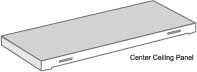
CENTER CEILING PANELS
Available in 24" and 36" wide in various lengths.
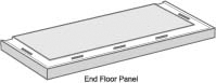
END FLOOR PANELS
Available in 24" and 36" wide in various lengths.
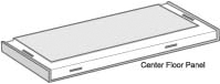
CENTER FLOOR PLANEL
Available in 24" and 36" widths in various lengths.
Installation Instructions
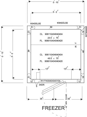
A plan view showing proper location of all panels is enclosed with the shipment. Before placing any panel into position, check the plan view for its location. The basic requirement for erection of a walk-in box is to have a level floor.
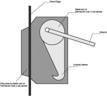
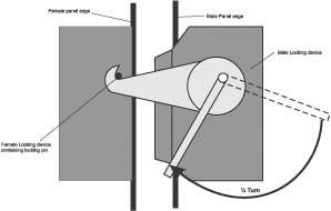
Learning the Operation of the Permanent Cam Lock System:
Before starting the assembly of the panels, make sure that the locking devices are at the stop position. To do so, turn the locking devices counter-clockwise, using a wrench, with force, until it stops moving any further.
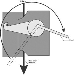
Push panels together and turn wrench ¼ turn clockwise. This will engage the male locking device "arm" over female locking device "pin".
Keep turning the wrench for another _ of a turn until the wrench stops moving any further.
If there are any problems during the operation of cam locks, turn the wrench counter-clockwise with force until it stops moving any further. This will put the locking device at its original position and you can try to assemble the panel again by moving the wrench in a clockwise direction.
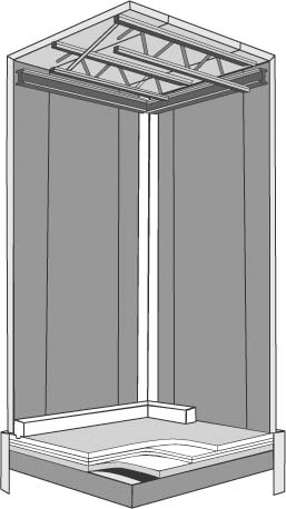
Floor Installation
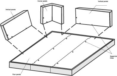
First of all mark the size of the construction area. Make sure the floor panel is level to the high point of the concrete slab. Put shims under the corners and across the panel joints to make sure that the panels are level. Shims should not be installed at more 23" distance from each other. If floor is level and there is no need to use shims, lay a 6 mil polyethylene sheet or 50 pounds asphalt paper between floor panels and existing floor. After making sure that the first floor end panel is at proper level put the next floor panel according to the plan view, locking each panel to the adjoining panels until the floor is assembled. Double check the levelness and square ness and adjust if necessary.
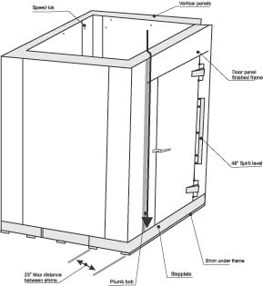
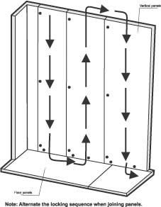
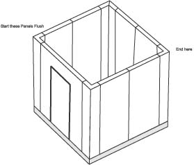
Vertical Panel Installation
First of all mark the size of the construction area. Make sure the floor panel is level to the high point of the concrete slab. Put shims under the corners and across the panel joints to make sure that the panels are level. Shims should not be installed at more 23" distance from each other. If floor is level and there is no need to use shims, lay a 6 mil polyethylene sheet or 50 pounds asphalt paper between floor panels and existing floor. After making sure that the first floor end panel is at proper level put the next floor panel according to the plan view, locking each panel to the adjoining panels until the floor is assembled. Double check the levelness and square ness and adjust if necessary.
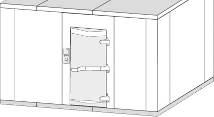
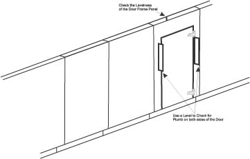
Door Frame Panels
To install the door frame panels follow the plan view to place the door frame at the right position. Lock the door frame to the wall panels check the levelness of door frame panels by using a spirit level.
Door frame panels contain a blocking between the door and the frame for protection. Do not remove this blocking unless the door frame panel is locked to both adjacent wall panels. Finalize wall panel installation at this stage. After checking that all the wall panels are at flush, fully lock the wall panels to the floors.
Installation of Ceiling Panels
To install the door frame panels follow the plan view to place the door frame at the right position. Lock the door frame to the wall panels check the levelness of door frame panels by using a spirit level.
Door frame panels contain a blocking between the door and the frame for protection. Do not remove this blocking unless the door frame panel is locked to both adjacent wall panels. Finalize wall panel installation at this stage. After checking that all the wall panels are at flush, fully lock the wall panels to the floors.
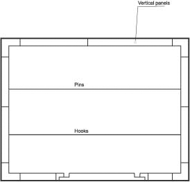
Sample View Plan
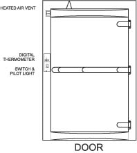
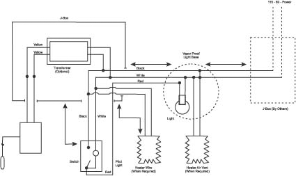
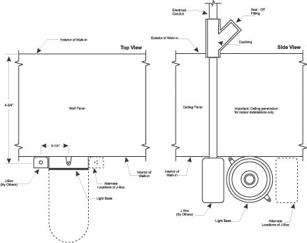
Electrical Connections
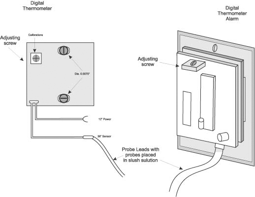
Digital Thermometer
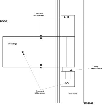
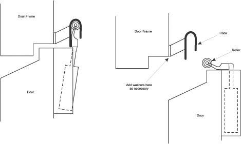
Door Hinges
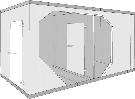
Foster Partitions
Foster Cold Storage Halls
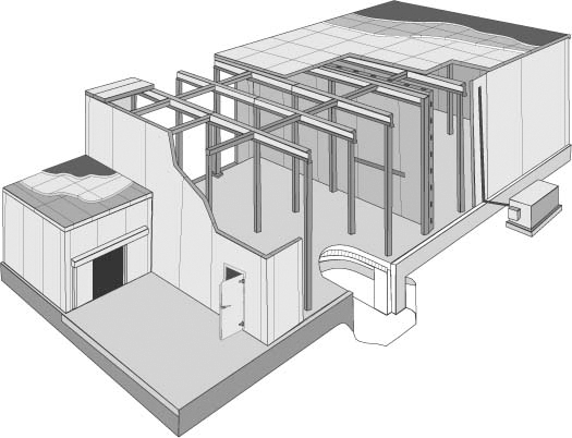
Foster Building Construction